
This month Brian Long takes you on a tour of the TCanvas class to see how you can do simple graphics in your Kylix applications.
This article first appeared in Linux Format Issue 28, June 2002.
Click here to download the files associated with this article.
If you find this article useful then please consider making a donation. It will be appreciated however big or small it might be and will encourage Brian to continue researching and writing about interesting subjects in the future.
Graphics are an important part of many applications but so far we have only looked at adding various controls to Kylix forms. This month we turn our attention to doing a bit of drawing. Clearly there are various levels we could take this. Advanced graphics and rendering can be achieved using OpenGL but we will start things off looking at the humble TCanvas object.
A canvas object is used in objects that need to render an image, so a form has a canvas as does a TPaintBox component and a TBitmap object (among many others).
The canvas offers a variety of methods for drawing lines, rectangles, ellipses, chords, circle segments, polygons, Bezier curves and for writing text. It uses a pen object to draw lines and shape boundaries, a brush for filling areas with a colour or pattern and a font for writing text. The pen, brush and font objects have their own properties to customise their attributes and they themselves are exposed through TCanvas properties.
To get something straightforward out of the TCanvas class our first example will be to draw the Union Jack on the background of the form. You'd be forgiven if you thought that this would be quite straightforward (a couple of differently coloured crosses laid on top of each other) but the flag has very particular specifications that give it the correct look. We found information on how to accurately draw the flag at http://www.jdawiseman.com/papers/union-jack/union-jack.html.
We'll use code that produces a faithful rendering of a Union Jack but first we should see how to use the canvas. Whenever you need to update an item that has a canvas you can simply set the relevant properties and call the appropriate methods of the TCanvas object available through the Canvas property to draw whatever you need. For example, this draws a purple rectangle with a red border from point (10,10) to point (300,300):
|
In the case of a form or a paint box component you need to update the canvas in response to the OnPaint event, which indicates it needs redrawing. CLX sends the OnPaint event whenever a section of the form becomes invalid, such as restoring a minimised form or moving a window from in front of the form. You can see what area actually needs redrawing by checking the ClipRect property, potentially allowing you to optimise the form re-drawing and making the application more responsive.
Correspondingly our Union Jack will be rendered on a form's canvas by its OnPaint event:
|
The OnPaint event handler first checks to see if the form has been narrowed down to nothing (ClientWidth would be 0) or shortened to nothing (ClientHeight would be 0). If either of these is true there is nothing to do so Exit is used to leave the event handler.
When we get round to drawing the Union Jack it needs to maintain a fixed aspect ratio (the width must be twice the height). Since the form can be resized to any proportions we will draw the largest flag possible in the centre of the available space. This means that as the form is resized there may be some blank space above and below the flag or to the left and right of it. The blank space will need to be refilled to erase parts of previously drawn flags of different dimensions, so we achieve this by drawing a filled rectangle over the entire form before starting to draw the flag.
The code sets the brush colour of the form's canvas to be the form's colour and then uses the brush to fill a rectangle that covers the form's client area (the ClientRect property returns this information as a TRect). FillRect does not draw the edges of the rectangle using the pen colour.
Next it moves on to identify the largest rectangle with the appropriate aspect ratio that can be drawn on the form; this is stored in the TRect record variable R set up by the Rect function. Once the size is identified the TRect is adjusted to ensure the rectangle is placed centrally in the form.
The final job is to pass the form's canvas and the size rectangle to the DrawUnionJack procedure, found in a separate unit called UnionJack.pas. DrawUnionJack is responsible for drawing a Union Jack on the specified canvas in the specified rectangle. It doesn't verify that the rectangle has the correct proportions but the OnPaint handler ensures this. The information shown on the aforementioned Web site explains the appropriate relationships between the placement and size of all the markings and the width and height of the flag.
After a pencil-and-paper session involving head scratching and strained attempts to recall some elementary trigonometry we came up with some code to do the job. Each part of the flag is drawn in turn using appropriate canvas operations and simple arithmetic, but there are a couple of trigonometric calculations that are required each time. To avoid repeating these unnecessarily, they are calculated in advance (in the unit initialisation section) and assigned to variables that are private to the UnionJack unit.
The code looks like this, but sections of it have been snipped for brevity. You can see the entire code in the SimpleGraphics.dpr project on this month's disk.
|
You can see the code declares some additional local variables for the left, top, right, bottom, width, height (as well as 1/3 and 2/3 of the height) of the bounding rectangle to allow briefer expressions to be written. Since most of the code involves calls to TCanvas methods or accessing TCanvas properties, a with statement is used to enter the scope of the canvas object before starting on the drawing code.
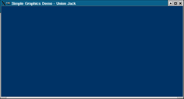
We'll take the drawing code a section at a time (the comments in the source should help you navigate it). Firstly the blue background is achieved by filling the entire rectangular area with an appropriate colour. This is specified to be Pantone 280, which equates to a TColor value with no red content, but with a green value of 51 and a blue value of 102. TColor values can be created easily by the RGB helper function. As you can see, a TColor has the red value in the low byte, then the green value and then the blue value.
|
With not much done yet, all we have is the background of the flag (see Figure 1). The next job is to get the thick, white diagonals which act as the border for the crosses of St. Andrew (a diagonal white cross, conveniently the same colour as the border) and St. Patrick (a diagonal red cross).
Figure 1: The flag background set up
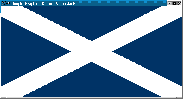
The pen and brush are set to white for this job and then some calculations precede the plotting of the required polygons. Polygons are drawn by supplying an array of TPoint records that indicate the vertices of the polygon. The Point function is helpful in creating a TPoint from a pair of X and Y co-ordinates. If you look at the result in Figure 2 you can see that each diagonal has 6 vertices, but the Polygon method requires one of points to be specified twice, once as the first point and once again as the last point.
Figure 2: The diagonal borders in place
Inside these diagonal borders are placed the crosses of St. Andrew and St. Patrick (and later the cross of St. George will be drawn over everything else).
These two crosses are interleaved in an odd way if look at it (see Figure 3). If you examine the paths of the red sections you will see they are not symmetrical. The idea is that in each corner within the white border you find a section of a red cross and a section of a white cross (which will obviously not be explicitly visible). At either end of each diagonal the relative positions of these crosses are swapped, which leads to some messy drawing code. If they were not swapped we would be able to just draw two diagonal red strips, but as it is we have to do four individual sections.
Figure 3: St. Patrick and St. Andrew taken care of
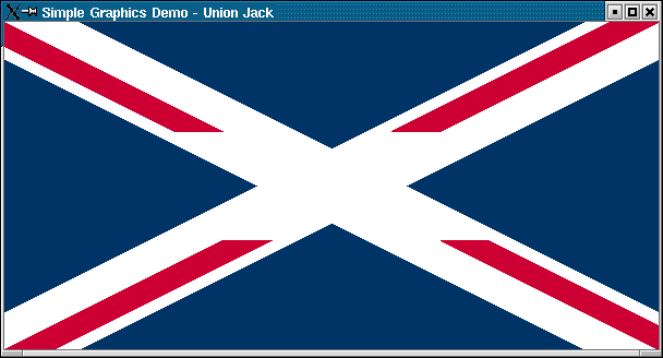
Each red quadrilateral must be drawn individually to get the required layout. Also, the official colour is Pantone 186, which is approximated using an RGB colour with a red value of 204 and a blue value of 51.
With two of the crosses out of the way, the border for St. George's cross can be drawn. This is just a pair of rectangles and gives Figure 4.
Figure 4: The border for St.George's cross
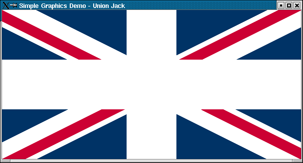
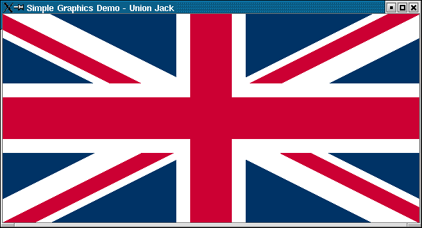
The final job is to draw in the St. George cross itself, involving nothing more than 2 further filled rectangles (as shown in Figure 5).
If you run the program you will find the form is resizable and as you resize, the Union Jack is drawn as large as possible keeping the correct aspect ratio.
The problem with this approach to drawing is that each individual change to the canvas is drawn onscreen individually, causing many screen updates. In this case eleven things happen onscreen each time the flag is drawn (background fill, two diagonal white strips, four diagonal red quadrilaterals, two white strips and two red strips). With a more complex image things would get very sluggish and flickery.
To overcome this problem it makes sense to use a background bitmap (an off-screen bitmap). This is a TBitmap object that represents the image we are creating. The bitmap object is an in-memory matrix of pixels that we can set up using its canvas object. When the image is complete we can draw that on the form causing only a single screen update.
Another issue is the excess drawing done in this example, thanks to the form's OnPaint event handler executing a FillRect call to fill the entire client area. There was good reason for this statement - it was designed to fill the gaps left when the form is resized and the flag doesn't occupy the whole client area. However it does mean that a lot of pixel plotting takes place pointlessly (most of this fill area is overdrawn by the flag).
Additionally, the form takes responsibility for ensuring the correct aspect ratio is maintained, and that really should belong in the flag drawing code.
SimpleGraphics2.dpr takes all these things into account. The form has a TBitmap defined as a private data field, which is constructed and destroyed in the form's OnCreate and OnDestroy event handlers respectively. The OnPaint event handler simply sets the bitmap to be the same size as the form's client area and then draws a flag on it. The bitmap object is then drawn on the form.
|
This project uses a unit called UnionJack2.pas, which is much the same as the original unit but contains a few updates. Firstly a new routine has been added that checks the aspect ratio of a rectangle passed in using a TRect. If the ratio is 2:1 as it should be the routine returns True. If not it returns False and sets up more information.
|
CheckAspectRatio defines three out parameters (they are much the same as var parameters but are used only to pass information out of a routine) that return the biggest rectangle the flag can occupy in the correct aspect ratio and the gaps either side, if there are any. The flag drawing routine can use this information to more efficiently paint its image on the canvas and fill in the rest of the area.
The start of the modified routine is shown below. As you can see, an additional background colour parameter is defined to specify the colour to fill in the extra space, and it has a default value of clBlack to save you specifying the colour unless you want something different.
|
This gives a better effect at run-time with each redraw being somewhat quicker (noticeable if you quickly resize the form larger and smaller).
If we don't want a single flag (or any bitmap for that matter) but instead want an image tiled across our form, then we can also readily accommodate this. SimpleGraphics3.dpr achieves this by setting up the flag in an off-screen bitmap in advance.
|
The OnPaint event is responsible for tiling this bitmap across the form whenever the form needs redrawing. This can be done very conveniently with the TiledDraw canvas method:
|
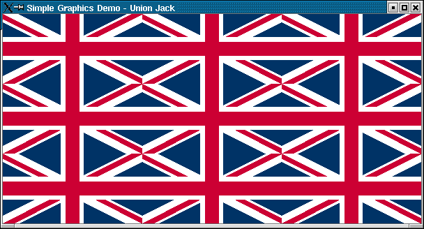
The downside with this method is that it offers no option to insert a small gap between each image (see Figure 6).
Figure 6: A tiled bitmap, but with no gaps...
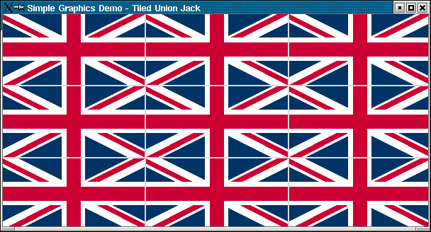
So instead, the tiling code logic is implemented by hand and gives the result in Figure 7:
|
Figure 7: A much better tiled effect
Of course we can use these principles to provide us a doodling opportunity (by way of a simple scribbling/drawing program). The project we are working towards is Scribble.dpr on the disk. It lets the user choose a pen width and colour and doodle over the form. A background bitmap is used to ensure the picture doesn't disappear when the form is covered (even by parts of its own menu).
The important parts of the code are the mouse event handlers (OnMouseDown, OnMouseUp and OnMouseMove), but let's first check the form events (OnCreate, OnDestroy and OnPaint).
|
When the form is created a background bitmap is created as large as the screen (to cater for the form being resized or maximised) and the pen of its canvas is set to have a default width of 1 and a red colour.
The OnDestroy handler ensures the bitmap is tidied away.
The OnPaint handler copies a portion of the background bitmap onto its canvas, as large as the form's exposed client area (there's no point copying pixels that won't be drawn). However you could alternatively write:
|
Now let's see what the mouse handlers do. The user starts drawing by pressing the left mouse button down, so if that happens a form data field (Drawing) is set to True to indicate drawing is happening. Additionally the LastPos field is set to the current mouse location. The Drawing flag is reset to False if the user releases the left mouse button.
When the mouse is moved whilst drawing is ongoing, the cursor is moved back to the last recorded mouse position and then a line drawn over to the current mouse position. The new position is recorded in the LastPos field so we know where to move back to then time the mouse is moved.
|
The form has a simple menu on it to adjust the pen width and colour. The Color... menu item invokes a colour selection dialog to let the user choose any supported colour. The Width menu item is a submenu with five menu items within it, allowing various widths to be chosen (see Figure 8).
Since they act as a set of mutually exclusive items (like radio buttons) each of them had its GroupIndex set to 1 so they all reside in a group. Additionally their RadioItem properties were set to True and they all share the same event handler (PenWidthClick in the code below).

|
Each menu item's Tag property is set to the value that needs to be assigned to the pen width (1 to 5 in this case). The event handler assigns Tag to the pen width and then checks the selected menu item. RadioItem being True ensures that when one of the menu items' Checked properties is set to True all the others are set to False.
It is clear that this is a very minimalist application and it is left as an exercise for the reader to add more interesting features, such as an option for starting a new doodle and options for drawing lines and circles and rectangles. You can also offer to save the bitmap to a file chosen from a save dialog (check out the TBitmap methods).
We have now looked at some simple drawing operations using the TCanvas object. You can see more drawing in the Clock demo that is installed along with Kylix (look in Kylix's demos directory).
Next month we'll look at some simple CLX animation. In the meantime, if there is something about Kylix Open Edition you want to see covered here, drop us an email and we'll try our best to incorporate it into a future instalment.
Brian Long used to work at Borland UK, performing a number of duties including Technical Support on all the programming tools. Since leaving in 1995, Brian has spent the intervening years as a trainer, trouble-shooter and mentor focusing on the use of the C#, Delphi and C++ languages, and of the Win32 and .NET platforms. In his spare time Brian actively researches and employs strategies for the convenient identification, isolation and removal of malware.
If you need training in these areas or need solutions to problems you have with them, please get in touch or visit Brian's Web site.
Brian authored a Borland Pascal problem-solving book in 1994 and occasionally acts as a Technical Editor for Wiley (previously Sybex); he was the Technical Editor for
Mastering Delphi 7
and
Mastering Delphi 2005
and also contributed a chapter to Delphi for .NET Developer Guide
.
Brian is a regular columnist in The
Delphi Magazine and has had numerous articles published in Developer's Review,
Computing, Delphi Developer's Journal
and EXE Magazine. He was nominated for the Spirit
of Delphi 2000 award.